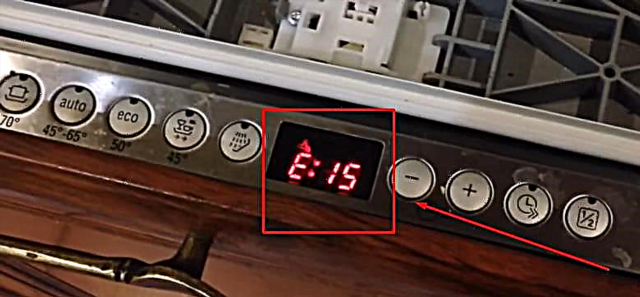
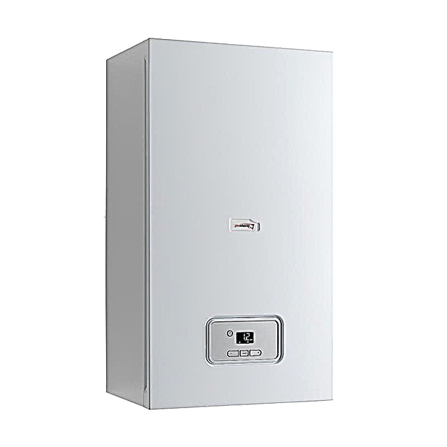
The Junkers boiler is prone to malfunctions in the same way as other equipment. The manufacturer simplified the search for the cause of the problem by developing a self-diagnosis system. Any malfunction is indicated on the display by an error code. You just need to find out the meaning of the code, after which either repair the equipment, or call the master at home.

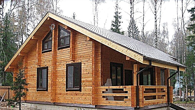
Installation and operation of gas boilers Junkers
Junkers brand boilers are available in two versions: classic and condensing.
A series of classic units include Ceraclass Comfort, Ceraclass Exellence, Junkers Euroline. These are single-circuit and double-circuit models mounted on a wall. Open and closed chambers can be connected to the main chimney or vent gases through a hole in the wall.
The design is equipped with a copper heat exchanger and a circulation pump that pumps liquid into the heating system. There is also a plate radiator for heating water.
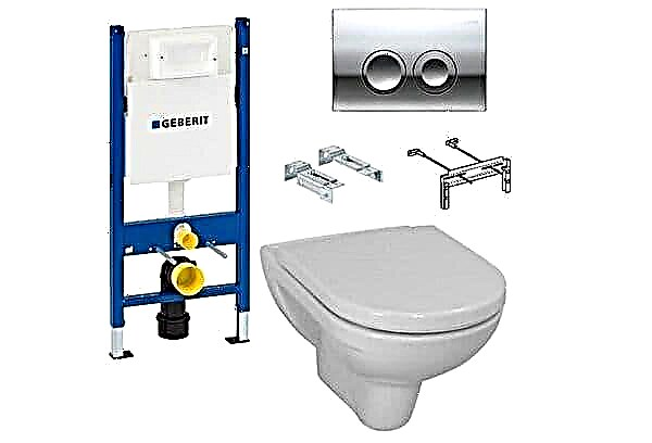
Cerapur Smart, Comfort, ACU are condensing boilers. This system provides fuel economy through the use of steam. Wall and floor devices are equipped with condensate collectors. The principle of the system is shown in the picture:

The output of combustion products occurs through a coaxial chimney. Some models have remote control.
Malfunction codes
You can find the interpretation of the values in the instructions and our table.
| Error code (LED flashes) | Value | Solutions |
| Junkers Euroline | ||
| 45 (alternating glow of diode 90). | Bad traction. | For closed models:
For atmospheric cameras:
|
| 60 | Faulty electronic module. | The ignition resistor or other element may have burned out. Diagnostics of the electronic part is required. |
| 75 | Damage to the main module. | Damage to the ignition circuit, ionization. Humidity on the board is removed by drying the element. |
| 90 | Problems with temperature limiter. | Checking and replacing:
|
| Junkers Eurostar, Junkers Ceraclass | ||
| AA | The flow temperature in the heating system is above normal. Low current of water. | What to do:
|
| A4 | Poor combustion products. | Something is preventing the exhaust of gases from the chamber; clean the system. |
| A7 | Damage to the hot water temperature sensor. | Check the parts, its contacts and install a new element if necessary. |
| A8 | The connection of the regulator is broken. | Regulator replacement. |
| A9 | The temperature sensor is not installed correctly. | Install the sensor correctly. |
| Ad | There is no connection with the boiler temperature sensor. | Inspection of contacts, connections, wiring. Diagnostics of sensors. |
| C4 | The pressure switch is broken. | Inspection of the switch, wiring, tube integrity. |
| C6 | Fan breakdown. | The fan in closed chambers is responsible for the exhaust and discharge of air. It is necessary to find out the cause of the breakdown and carry out repairs. |
| SS | Communication with an external thermometer is not detected. | Tighten the contacts, make sure the integrity of the wiring and the health of the thermometer. |
| CE | The pressure in the heating system has decreased. | Measure indicators, and add water if necessary. |
| CF | The pressure sensor has tripped. | Similar actions CE. |
| E2 | The sensor that detects the temperature of the feed water is damaged. | Make sure that the wires are not damaged and that the contacts are closed. |
| Error E9 | The heat exchanger or flue gas thermostat has tripped. | Inspection in progress:
Cleaning the chimney shaft. |
| EA | The flame in the burner is not detected. |
|
| F1 | Data error. | Reboot the boiler. |
| F7 | The device is turned off, but the flame is detected. | System restart. |
| FA | The gas is off, but the system shows a flame. | Actions are similar to F7. |
| Fd | The Reset key is accidentally pressed. | Click again. |
| Junkers with board S4962 | ||
| E01 / E02 | The boiler does not recognize the flame; indication of its presence with blocked fuel. | |
| E03 | Overheat. | The contacts with the overheating sensor broke. Diagnostics of elements. |
| E04 | The pressure switch circuit is closed until ignition. | |
| E05 | The pressure switch does not work. The fan does not rotate. | Check circuit, fan and pressure switch. |
| E06 | The air sensor circuit does not close during 5 ignition attempts. | Proceed according to E05. |
| E07 | Fan protection turned on. | |
| E08 | Incorrect operation of the ionization circuit. | Diagnostics and repair. |
| E09 | Incorrect operation of the GC scheme. | |
| E10 | EEPROM memory error. | Install a new module. |
| E30 (violation of wiring); E31; E32 | Thermostat NTC CH heating. | Checking and repairing chains. |
| DHW sensor NTC DHW. | ||
| Flue gas sensor NTC Flue. | ||
| E33 | Overheating in terms of heating. | Descaling the heat exchanger, adjusting the temperature on the panel. |
| E34 / E35 | Insufficient mains voltage. | Wait for the feed to return. |
| E37 | Overheating of combustion products. | Inspect the sensor, patency of the withdrawal paths. |
To avoid premature damage, experts recommend:
- Perform boiler maintenance at least once a year;
- Install water purification filters;
- To clean knots of dust, soot, scale;
- To control the patency of the exhaust ducts;
- Do not set the heating temperature above 60 degrees.
Be mindful of your technique. Do not delay the repair: if you notice signs of a problem, try to fix it. Or contact the service center.